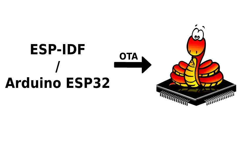

Over-the-air switch from ESP-IDF to micropython
Or how to save hours and hours of unscrewing and reassembling enclosed devices in the field just for a decision of code language change

Introduction
In this blog post we will go over an interesting solution on how to switch from Arduino or esp-idf firmware to micropython Over-The-Air on an ESP32.
Imagine having tens or hundreds of devices deployed in the field that are running firmware based on Arduino for ESP32 or esp-idf. Those devices are enclosed in a box that does not provide access to the hardware board. Their only means of interaction is the esp-idf OTA mechanism. Meanwhile, because of business decision, it is decided to switch the firmware from C++ implementation (Arduino or esp-idf) to a micropython-based firmware.
It sounds like just an Over-The-Air update, right? Unfortunately, it is not that simple.
The problem
Both firmwares use different partition tables that are not compatible with each other. Even if they were compatible, micropython firmware requires larger application partition.
The solution
The solution comes by building an intermediate application that will first adapt the partition table of the device and then flush the micropython firmware. This application will be based on simple_ota_example and can be found on Github.
ESP-IDF & micropython version selection
Key decision before making any change is the correct selection of esp-idf and micropython version. It is essential to pinpoint the exact ESP-IDF version that the already used bootloader was compiled with, as the bootloader does not support booting apps from older versions of ESP-IDF. Since the bootloader of the device cannot be altered over-the-air, this defines the minimum ESP-IDF version that the application must have. Micropython is based on ESP-IDF, thus the minimum ESP-IDF version dictates the minimum micropython version.
There is also a maximum ESP-IDF/micropython version boundary. Bootloader and application must use the same ESP-IDF major version. Thus, a bootloader built with ESP-IDF v3.3.2 cannot run micropython built with v4.x. (this info is based on personal tests, it is not backed by any official documentation)
Here is a quick table as a reference to help the version selection:
| ESP-IDF | ESP-IDF / Arduino | Micropython |
|---|---|---|
| 4.4.2 | 2.0.5 | - |
| 4.4.1 | 2.0.4 | - |
| 4.4.1 | 2.0.3 | - |
| 4.4-beta1 | 2.0.2 | - |
| 4.4 | 2.0.1 | 1.19 |
| 4.4-dev | 2.0.0 | - |
| 4.3.2 | - | - |
| 4.2 | - | 1.15, 1.16, 1.17, 1.18 |
| 4.1.1 | - | 1.15, 1.16, 1.17, 1.18 |
| 4.0.2 | - | 1.15, 1.16, 1.17, 1.18 |
| 4.0.1 | - | 1.13, 1.14 |
| 3.3.5 | 1.0.6 | - |
| 3.3.2 | - | 1.13, 1.14 |
| 3.3 | 1.0.5 | 1.11, 1.12 |
| 3.2 | 1.0.4 | 1.1 |
| 3.2 | 1.0.3 | - |
| 3.2 | 1.0.2 | - |
In a real-life example that we had handled, the client had ESP32 Arduino v1.0.6 (ESP-IDF v3.3.5). That version was higher than the closest micropython compiled with IDF v3.x (1.13 or 1.14) so we had to port micropython 1.14 to use IDF v3.3.5 instead of IDF v3.3.2.
The partition table layout
As a starting point, consider the partition table of the device that is configured for OTA (for extended details see Espressif Documentation). It contains 3 important partitions, ota_0, ota_1 and spiffs. During updates, the device alternates the usage of ota_0 and ota_1 to boot from one and write to the other. The spiffs is used by the application to store data.
| Name | Type | SubType | Offset | Size |
|---|---|---|---|---|
| nvs | data | nvs | 0x9000 | 0x5000 |
| otadata | data | ota | 0xe000 | 0x2000 |
| app0 | app | ota_0 | 0x10000 | 0x140000 |
| app1 | app | ota_1 | 0x150000 | 0x140000 |
| spiffs | data | spiffs | 0x290000 | 0x170000 |
During a partition update, the running application partition is advised not to be tampered with, thus the most optimal approach is to apply the changes when running from ota_0 partition to have the most continuous memory ahead to format. The goal is to expand ota_1 (app1) partition, delete spiffs and create the remaining space as fat (vfs) that is required by micropython. The target partition table looks like:
| Name | Type | SubType | Offset | Size |
|---|---|---|---|---|
| nvs | data | nvs | 0x9000 | 0x5000 |
| otadata | data | ota | 0xe000 | 0x2000 |
| app0 | app | ota_0 | 0x10000 | 0x140000 |
| app1 | app | ota_1 | 0x150000 | 0x180000 |
vfs | data | fat | 0x2D0000 | 0x100000 |
The ota_1 partition size should be adjusted based on the size of the micropython.bin that needs to be flushed. In our case the size was 1464336 (0x165810) bytes and for safety reasons 0x180000 was selected. The vfs starts at the end of ota_1 (offset + size) and its size is the size of device flash (e.x. 4MB) minus the starting offset of vfs.
Repartitioner
So far, the esp-idf and micropython have been selected as well as the target partition table schema. It is time to put that all together into the repartitioner application.
Here are the steps that repartitioner follows:
- The device is running the initial firmware and is scheduled to update with repartitioner.bin
- The repartitioner.bin gets written
- Reset
- At each boot, repartitioner checks the current partition table, identifies the boot partition (ota_0 or ota_1) and checks the existence of vfs partition
- If the boot partition is ota_0 and the ota_1 size is already changed move to step 11
- If the boot partition is ota_0 move to step 8 else move to next step
- Download and apply again repartitioner.bin to force it to boot from ota_0 next time
- Reset
- Having ensured that boot partition is ota_0, proceed with the changes
- write the new partition table:
-
spi_flash_write(CONFIG_PARTITION_TABLE_OFFSET, new_table, 0x1000);
-
- Erase memory of partition vfs. (Very important for the micropython!)
-
esp_err_t retNvs = spi_flash_erase_range(PARTITION_VFS_OFFSET, PARTITION_VFS_SIZE);
-
- Reset
- write the new partition table:
- Check that the boot partition is ota_0 and that ota_1 has the altered size to prove that all changes were completed
- The device is ready to receive the final firmware. Download & apply micropython.bin
- Reset
- Ready!
Adapt code to match use case + interesting/important configurations
- in the sdkconfig, It is essential to allow the application to write to protected memory regions, such as the partition table memory region.
- CONFIG_SPI_FLASH_WRITING_DANGEROUS_REGIONS_ALLOWED=y
- Define the WiFi credentials (in simple_ota_example.c)
- CONFIG_WIFI_SSID
- CONFIG_WIFI_PASSWORD
- Define the URL of the generated repartitioner binary and the binary of the target micropython firmware (in simple_ota_example.c). Our tests were executed over simple HTTP.
- CONFIG_EXAMPLE_FIRMWARE_UPGRADE_URL
- CONFIG_EXAMPLE_FIRMWARE_LOOP_URL
- Update the following partition table addresses used by checks and initializations (in repartition.h)
- PARTITION_OTA_1_TARGET_SIZE
- PARTITION_VFS_OFFSET
- PARTITION_VFS_SIZE
- Define the target partition table content by setting the byte array “final_table” as hex const char array (in repartition.h).
- To generate the bytes of the new partition table, including their checksum, the easiest way is to pick any esp-idf example, set it to use custom partitions.csv, define the desired partition table and build the application. After a successful build, the partition table binary will be placed at “build/partition_table/partition_table.bin”.
- Get the data from the binary file by using a HEX editor. In linux, ‘xxd’ console application can be used directly
xxd build/partition_table/partition_table.bin
- Extract the bytes in hex, format them into a const char array and update the “final_table” (in repartition.h)
The end
Having configured the above, the application is ready to be used!
Tip: This procedure works ideally if the micropython binary also has frozen modules generated by microfreezer (https://insigh.io/blog/how-to-freeze-the-unfreezable/). This way, as soon as it boots up, the flash memory will be filled with the required micropython scripts automatically.
Links
- Final application: https://github.com/insighio/esp-idf-repartitioner
- The initial code used for repartitioning: https://www.esp32.com/viewtopic.php?f=13&t=12004#p52962
- Esp-idf simple_ota_example used as base project: https://github.com/espressif/esp-idf/tree/master/examples/system/ota/simple_ota_example
- Extra information: https://esp32.com/viewtopic.php?t=11482
- Esp-idf OTA mechanism: https://docs.espressif.com/projects/esp-idf/en/latest/esp32/api-reference/system/ota.html

